Node.js Raspberry Pi - Components
What are Components?
Components are parts of a larger whole. In this chapter, we explain the different components we use in our tutorial.
The Raspberry Pi and GPIO Pins
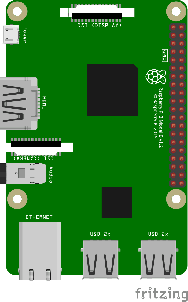
This is an illustration of the Raspberry Pi 3.
The GPIO pins are the small red squares in two rows on the right side of the Raspberry Pi, on the actual Raspberry Pi they are small metal pins.
Input pins are like switches that you can turn on or off from the outside world (like a on/off light switch).
Output pins are like switches that the Raspberry Pi can turn on or off (like turning on/off a LED light).
The Raspberry Pi 3 has 26 GPIO pins, the rest of the pins are power, ground or "other".
The pin placements correspond with the table below.
Raspberry Pi B+, 2, 3 & Zero
| 3V3 | 1 | 2 | 5V |
| GPIO 2 | 3 | 4 | 5V |
| GPIO 3 | 5 | 6 | GND |
| GPIO 4 | 7 | 8 | GPIO 14 |
| GND | 9 | 10 | GPIO 15 |
| GPIO 17 | 11 | 12 | GPIO 18 |
| GPIO 27 | 13 | 14 | GND |
| GPIO 22 | 15 | 16 | GPIO 23 |
| 3V3 | 17 | 18 | GPIO 24 |
| GPIO 10 | 19 | 20 | GND |
| GPIO 9 | 21 | 22 | GPIO 25 |
| GPIO 11 | 23 | 24 | GPIO 8 |
| GND | 25 | 26 | GPIO 7 |
| DNC | 27 | 28 | DNC |
| GPIO 5 | 29 | 30 | GND |
| GPIO 6 | 31 | 32 | GPIO 12 |
| GPIO 13 | 33 | 34 | GND |
| GPIO 19 | 35 | 36 | GPIO 16 |
| GPIO 26 | 37 | 38 | GPIO 20 |
| GND | 39 | 40 | GPIO 21 |
Legend
| Physical Pin Number |
| Power + |
| Ground |
| UART |
| I2C |
| SPI |
| GPIO |
| Do Not Connect |
The Breadboard
A breadboard is used for prototyping electronics, it allows you to create circuits without soldering. It is basically a plastic board, with a grid of tie-points (holes). Inside the board there are metal strips connecting the different tie-points in specific ways.
In the illustration below we have highlighted some of the sections with different colors. This is to show you how the grid is connected.
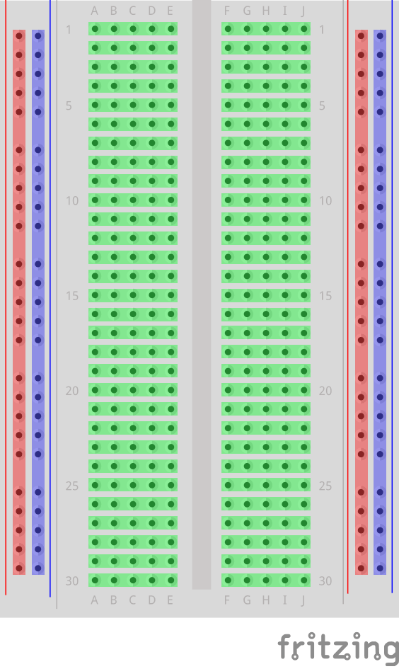
The different sections of the breadboard:
- On the left, and right, side there are 2 columns of tie-points. All the tie points in each of these columns are connected.
- The Power Bus - The columns highlighted with red. There are usually used to connect power to the Breadboard. Since the entire column is connected, you can connect power to any of the tie-points in the column.
- The Ground Bus - The columns highlighted with blue. There are usually used to connect Ground to the Breadboard. Since the entire column is connected, you can connect ground to any of the tie-points in the column.
- Rows of connected Tie-Points - The rows highlighted with green. The tie-points of each of these rows are connected, but not the entire row! The left side tie-points are connected (A-B-C-D-E), and the right side tie-points are connected (F-G-H-I-J).
- In the center of the Breadboard there is a Trench, this separates the left and right rows. The width of the trench is designed so that many Integrated Circuits fit across it.
Other Electrical Components
Through Hole LEDLight emitting diode (LED). An LED is a diode that emits light when a voltage is applied to it. In our example we use a Through Hole LED. They have a positive (called Anode), and a negative (called Cathode) pin. The longer leg on the LED should indicate the positive pin. |

|
RGB LEDLight emitting diode (LED). An LED is a diode that emits light when a voltage is applied to it. An RGB LED has 4 pins. One for each color (R = Red, G = Green, and, B = Blue), and a common cathode/anode. This one LED can display the pure colors, or with PWD to modulate and mix colors. |

|
Push ButtonA push button is a type of switch. A switch makes or breaks a connection an an electric circuit. |

|
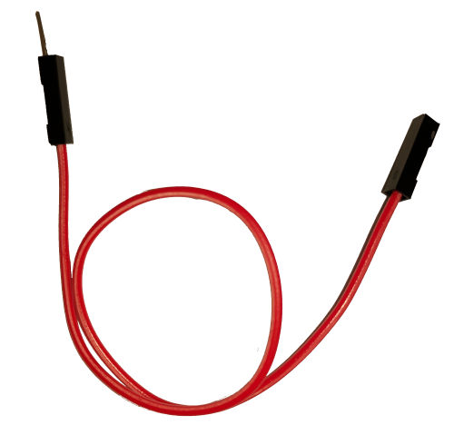
Jumper Wire - Female to MaleShort pieces of wire called jumper wires are used to make connections. Female to Male jumper wires can be used to connect from the GPIO on the Raspberry Pi to the Breadboard. |
|
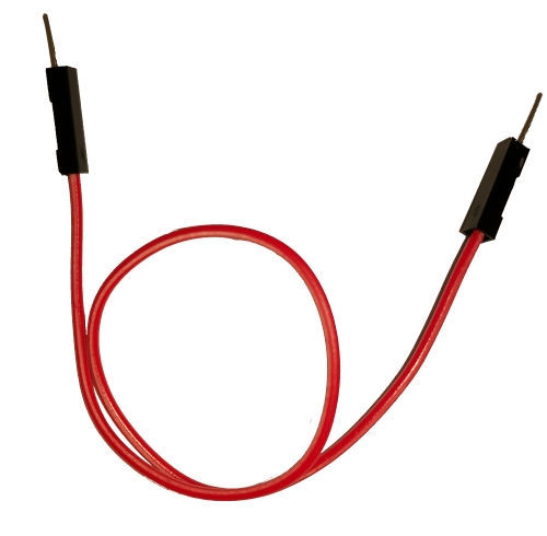
Jumper Wire - Male to MaleShort pieces of wire called jumper wires are used to make connections. Male to Male jumper wires can be used to make connections between different parts of the Breadboard. |
|
Resistor - 68 OhmResistors are used to reduce current, adjust signal levels, etc. This is a 68 Ohm resistor. |

|
Resistor - 220 OhmResistors are used to reduce current, adjust signal levels, etc. This is a 220 Ohm resistor. |

|
Resistor - 1k OhmResistors are used to reduce current, adjust signal levels, etc. This is a 1k Ohm resistor. |

|
Node.js Modules
|
onoff - GPIO access and interrupt detection with Node.js |
|
|
Socket.IO - real-time bidirectional event-based communication |
|
|
pigpio - wrapper for pigpio C library. Enables GPIO, PWM, servo control, state change notification and interrupt handling with Node.js |

